Introduction
Logic gates are the basic building blocks of any digital system. Logic gates are electronic circuits having one or more than one input and only one output. The relationship between the input and the output is based on a certain logic. Based on this, logic gates are named as:
- AND gate
- OR gate
- NOT gate
- NAND gate
- NOR gate
- Ex-OR gate
- Ex-NOR gate
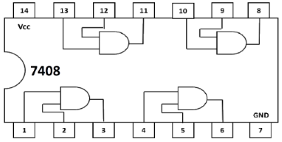
1. AND Gate
The AND gate is an electronic circuit that gives a high output (1) only if all its inputs are high. A dot (.) is used to show the AND operation i.e. A.B or can be written as AB

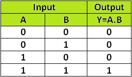
A simple 2-input logic AND gate can be constructed using IC 7408
2. OR Gate
The OR gate is an electronic circuit that gives a high output (1) if one or more of its inputs are high. A plus (+) is used to show the OR operation.

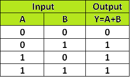
A simple 2-input logic OR gate can be constructed using IC 7432
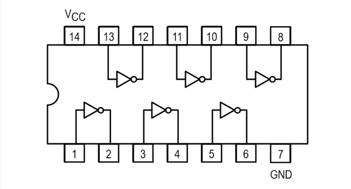
3. NOT Gate
The NOT gate is an electronic circuit that produces an inverted version of the input at its output. It is also known as an inverter. If the input variable is A, the inverted output is known as NOT A. This is also shown as A' or A with a bar over the top.

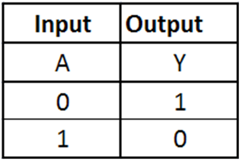
A simple 1-input logic NOT gate can be constructed using IC 7404
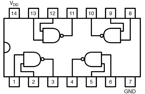
4. NAND Gate
This is a NOT-AND gate which is equal to an AND gate followed by a NOT gate. The outputs of all NAND gates are high if any of the inputs are low. The symbol is an AND gate with a small circle on the output. The small circle represents inversion.


A simple 2-input logic NAND gate can be constructed using IC 7400
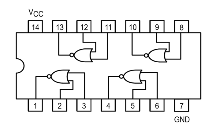
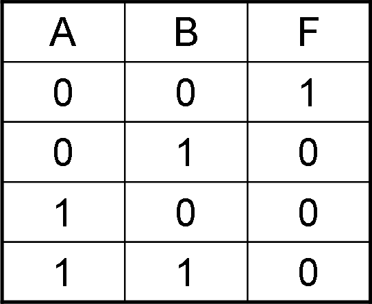
5. NOR Gate
This is a NOT-OR gate which is equal to an OR gate followed by a NOT gate. The outputs of all NOR gates are low if any of the inputs are high. The symbol is an OR gate with a small circle on the output. The small circle represents inversion.

A simple 2-input logic NOR gate can be constructed using IC 7402